Windows Memory Introspection with IceBox
Virtual Machine Introspection (VMI) is an extremely powerful technique to explore a guest OS. Directly acting on the hypervisor allows a stealth and precise control of the guest state, which means its CPU context as well as its memory.
Basically, a common use case in VMI consists in (1) setting a breakpoint on an address, (2) wait for a break and (3) finally read some virtual memory.
For example, to simply monitor the user file writing activity on Windows, just set a breakpoint on the NtWriteFile function in kernel land.
Once triggered, you can retrieve the involved process and capture its corresponding callstack.
All these actions eventually require accessing the guest virtual memory.
Accessing this memory sounds quite simple at first sight. Nevertheless, the reality turns out to be a bit more complex on Windows.
Indeed, everyone has already heard about the paging mechanism.
Briefly, paging consists in backing up a physical memory page on the disk to make it available for further access in order to somehow increase the physical memory space. By default, Windows stores these backed up pages into paging files (by default pagefile.sys, also known as the swapping file).
Consequently, the whole content of a process virtual memory may not be directly accessible when a breakpoint is hit as some pages may have been paged out.
Disabling paging files is a well-known feature on Windows and seems to be a simple approach to keep all pages in physical memory. Unfortunately, as we will see through this article, this technique is not sufficient. Indeed, Windows implements several optimizations to deal with physical memory.
The first part of this article describes the Windows virtual address translation mechanism. More precisely, all the software states involved in the description of a physical memory page are described.
Then, in a second part, it focuses on how IceBox can automatically configure the OS during its initialization phase to offer full physical memory access of a Windows guest.
Windows Virtual Address Translation
The hardware part
Software memory management relies on the underlying hardware support. From a hardware point of view, the Memory Management Unit (MMU) is in charge of virtual address translation to access physical memory. For a complete description see the Intel® 64 and IA-32 Architectures Software Developer Manuals. Here, we just present the most common current case: 64-bits 4-level paging mode.
This translation process starts with the CR3 register and of course, a virtual address.
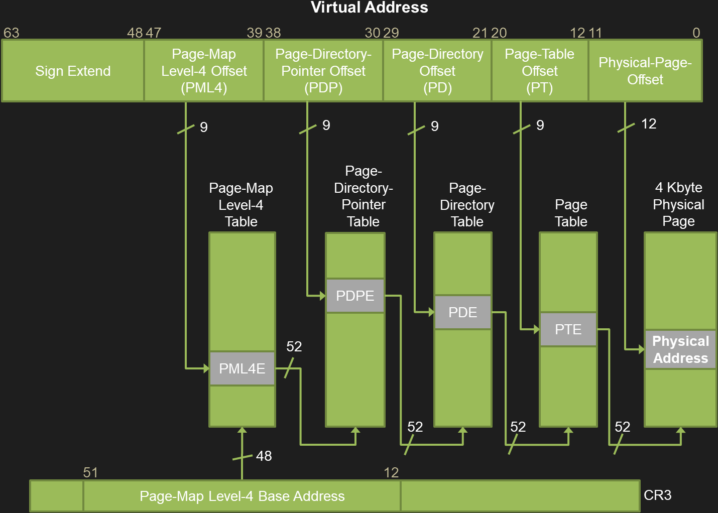
The upper 16 bits of the address are unused, the 48 following ones are split in 4 values of 9 bits which correspond to the 4 levels of the Page Table hierarchy:
- Level 0 is Page-Map Level-4 Offset (PML4).
- Level 1 is Page-Directory-Pointer Offset (PDP).
- Level 2 is Page-Directory Offset (PDP).
- Level 3 is Page Table Offset (PT).
The last 12 bits correspond to the offset in a page.
The whole process is illustrated in the next figure:
- The CR3 contains the Page-Map Level-4 Base-Address also known as the Directory Table Base (DTB) (bits 12 to 51).
- The PML4E gives the base of the Page-Directory-Pointer Table (PDPT) from which the PDPE can be read at the PDP offset.
- The PDPE gives the base of the Page-Directory Table (PDT) from which the PDE can be read at the PD offset.
- The PDE gives the base of the Page Table (PT) from which the PTE can be read at the PT offset.
At the end, the Page Table Entry (PTE) describes the state of a page in physical memory.
In Windows, this hardware state is defined by the _MMPTE_HARDWARE structure:
nt!_MMPTE_HARDWARE
   +0x000 Valid               : Pos 0, 1 Bit
   +0x000 Dirty1              : Pos 1, 1 Bit
   +0x000 Owner               : Pos 2, 1 Bit
   +0x000 WriteThrough        : Pos 3, 1 Bit
   +0x000 CacheDisable        : Pos 4, 1 Bit
   +0x000 Accessed            : Pos 5, 1 Bit
   +0x000 Dirty               : Pos 6, 1 Bit
   +0x000 LargePage           : Pos 7, 1 Bit
   +0x000 Global              : Pos 8, 1 Bit
   +0x000 CopyOnWrite         : Pos 9, 1 Bit
   +0x000 Unused              : Pos 10, 1 Bit
   +0x000 Write               : Pos 11, 1 Bit
   +0x000 PageFrameNumber     : Pos 12, 36 Bits
   +0x000 ReservedForHardware : Pos 48, 4 Bits
   +0x000 ReservedForSoftware : Pos 52, 4 Bits
   +0x000 WsleAge             : Pos 56, 4 Bits
   +0x000 WsleProtection      : Pos 60, 3 Bits
   +0x000 NoExecute           : Pos 63, 1 Bit
For our purpose, the only important bits are:
- The
Validflag indicating to the hardware that all the others bits are valid and the target physical page can be safely accessed. - The
PageFrameNumberstanding for the page index in physical memory.
When a page is valid, the physical address can easily be computed as follows:
PhysicalAddress =
_MMPTE_HARDWARE.PageFrameNumber* 0x1000 + PageOffset
The software part
In Windows, the Working Set (WS) is a key concept concerning memory management. It basically corresponds to the set of pages that can be accessed without incurring a page fault. Three types of WS exist: process, system and session one, each with its own limit.
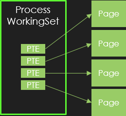
Throughout this article, we use the following simplified WS figure to illustrate how Windows virtual address translation behaves:
Here, we consider the working set of a single process.
For the sake of simplicity, this WS is represented on the left as a set of PTEs.
Each of theses PTEs refers to a valid page as represented on the right side. A valid PTE has the Valid bit set, in which case, the MMU plays its role and performs the translation to physical address.
When the Valid bit is not set, the MMU ignores all the other PTE flags and accessing such a page will result in a page fault.
This offers the possibility for the OS to use these bits for any purpose and especially to optimize the way it manages its memory.
As a consequence, Windows defines several internal states for a page through a specific union named _MMPTE:
nt!_MMPTE
   +0x000 u  :
      +0x000 Long         : Uint8B
      +0x000 VolatileLong : Uint8B
      +0x000 Hard         : _MMPTE_HARDWARE
      +0x000 Proto        : _MMPTE_PROTOTYPE
      +0x000 Soft         : _MMPTE_SOFTWARE
      +0x000 TimeStamp    : _MMPTE_TIMESTAMP
      +0x000 Trans        : _MMPTE_TRANSITION
      +0x000 Subsect      : _MMPTE_SUBSECTION
      +0x000 List         : _MMPTE_LIST
Apart from the already presented _MMPTE_HARDWARE, all the other structures represent software states for a PTE, used by the OS to implement several optimizations.
As detailed in the next sections, looking at the _MMPTE_SOFTWARE tells us what structure is to be considered:
nt!_MMPTE_SOFTWARE
   +0x000 Valid                : Pos 0, 1 Bit     //_MMPTE_HARDWARE
   +0x000 PageFileReserved     : Pos 1, 1 Bit
   +0x000 PageFileAllocated    : Pos 2, 1 Bit
   +0x000 ColdPage             : Pos 3, 1 Bit
   +0x000 SwizzleBit           : Pos 4, 1 Bit
   +0x000 Protection           : Pos 5, 5 Bits
   +0x000 Prototype            : Pos 10, 1 Bit    //_MMPTE_PROTOTYPE/_MMPTE_SUBSECTION
   +0x000 Transition           : Pos 11, 1 Bit    //_MMPTE_TRANSITION
   +0x000 PageFileLow          : Pos 12, 4 Bits
   +0x000 UsedPageTableEntries : Pos 16, 10 Bits
   +0x000 ShadowStack          : Pos 26, 1 Bit
   +0x000 Unused               : Pos 27, 5 Bits
   +0x000 PageFileHigh         : Pos 32, 32 Bits  //_MMPTE_SOFTWARE
The following sections are already well documented by the Rekall forensics project. However, we remind all the possible software PTE states involved in the Windows virtual address translation and their evolutions to mitigate recent CPU speculative execution flaws (CVE-2018-3615 L1 Terminal Fault, aka Foreshadow).
Transition PTE
In Windows, the Balance Set Manager (KeBalanceSetManager) is in charge of the Working Sets.
When the available physical memory falls under a certain threshold, this component can decide to remove some rarely used pages from the WS (see Windows Internals 7th edition chaper 5 : Memory Management for more information concerning the balance set manager).
This is achieved by changing the current state of a PTE from valid (_MMPTE.u.hard.Valid=1) to transition (_MMPTE.u.Hard.Valid=0 and _MMPTE.u.Soft.Transition=1).
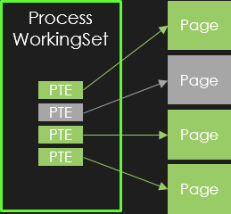
This step is illustrated in the next figure:
In gray, a previously valid page was removed from the working set and the corresponding PTE is marked in transition state.
Although the page cannot be directly accessed, its content is still present and valid in physical memory.
Upon access, a page fault is triggered which will restore the PTE state from transition to valid.
This transition state corresponds to a _MMPTE_TRANSITION structure:
nt!_MMPTE_TRANSITION
   +0x000 Valid            : Pos 0, 1 Bit     // 0
   +0x000 Write            : Pos 1, 1 Bit
   +0x000 Spare            : Pos 2, 1 Bit
   +0x000 IoTracker        : Pos 3, 1 Bit
   +0x000 SwizzleBit       : Pos 4, 1 Bit
   +0x000 Protection       : Pos 5, 5 Bits
   +0x000 Prototype        : Pos 10, 1 Bit
   +0x000 Transition       : Pos 11, 1 Bit    // 1
   +0x000 PageFrameNumber  : Pos 12, 36 Bits
   +0x000 Unused           : Pos 48, 16 Bits
In the transition state, the target physical address of a PTE is calculated as for a valid one:
PhysicalAddress =
_MMPTE.u.Trans.PageFrameNumber* 0x1000 + PageOffset
Paging file PTE
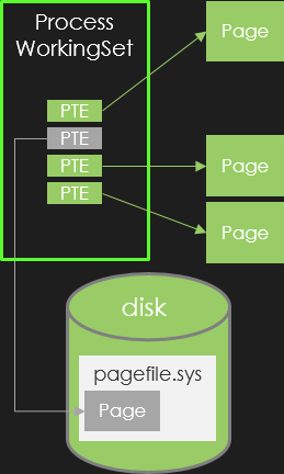
Later, a page in the transition state will be paged-out to a paging file located on the disk. This step frees the page from the physical memory and backs it up to the disk as illustrated by the following figure:
The corresponding structure is the already viewed _MMPTE_SOFTWARE with Valid, Prototype and Transition flags set to zero but a non null PageFileHigh.
nt!_MMPTE_SOFTWARE
   +0x000 Valid                : Pos 0, 1 Bit     // 0
   +0x000 PageFileReserved     : Pos 1, 1 Bit
   +0x000 PageFileAllocated    : Pos 2, 1 Bit
   +0x000 ColdPage             : Pos 3, 1 Bit
   +0x000 SwizzleBit           : Pos 4, 1 Bit
   +0x000 Protection           : Pos 5, 5 Bits
   +0x000 Prototype            : Pos 10, 1 Bit    // 0
   +0x000 Transition           : Pos 11, 1 Bit    // 0
   +0x000 PageFileLow          : Pos 12, 4 Bits
   +0x000 UsedPageTableEntries : Pos 16, 10 Bits
   +0x000 ShadowStack          : Pos 26, 1 Bit
   +0x000 Unused               : Pos 27, 5 Bits
   +0x000 PageFileHigh         : Pos 32, 32 Bits  // !=0
In this case, the only way to retrieve the page content is to read it back from the corresponding paging file.
By default, the OS defines one paging file by drive.
Each paging file is identified by an index.
When a page is backed, the target paging file index corresponds to the PageFileLow field and the page offset in the file (PageFileOffset) is resolved as follows:
PageFileOffset =
_MMPTE.u.Soft.PageFileHigh* 0x1000 + PageOffset
Demand-zero PTE
Instead of saving a zero-filled page, the OS simply keeps this information in the corresponding PTE structure.
When such a page has to be restored, the Balance Set Manager gets one from the zero page list to update the corresponding PTE.
This list of zero pages is maintained by the zero page thread (MiZeroPageThread) to satisfy demand-zero page faults.
A demand-zero page presents a non-null PTE value (_MMPTE.u.Long) but the following flags are set to zero in the _MMPTE_SOFTWARE structure: Valid, Prototype, Transition and PageFileHigh.
nt!_MMPTE_SOFTWARE
   +0x000 Valid                : Pos 0, 1 Bit     // 0
   +0x000 PageFileReserved     : Pos 1, 1 Bit
   +0x000 PageFileAllocated    : Pos 2, 1 Bit
   +0x000 ColdPage             : Pos 3, 1 Bit
   +0x000 SwizzleBit           : Pos 4, 1 Bit
   +0x000 Protection           : Pos 5, 5 Bits
   +0x000 Prototype            : Pos 10, 1 Bit    // 0
   +0x000 Transition           : Pos 11, 1 Bit    // 0
   +0x000 PageFileLow          : Pos 12, 4 Bits
   +0x000 UsedPageTableEntries : Pos 16, 10 Bits
   +0x000 ShadowStack          : Pos 26, 1 Bit
   +0x000 Unused               : Pos 27, 5 Bits
   +0x000 PageFileHigh         : Pos 32, 32 Bits  // 0
Prototype PTE
Prototype PTE aims at describing the memory represented by section objects.
A section object can be created by the CreateFileMapping function, opened by OpenFileMapping and mapped with MapViewOfFile.
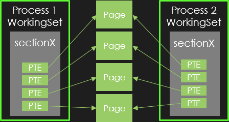
Basically, section objects correspond to shared memory as illustrated below:
We have two processes, each one owns the same section object (sectionX), which points to the same physical pages. Here, all the PTE are valid.
The difficulty concerning the OS is to synchronize the trimming of shared pages. Indeed, as several PTEs can reference the same physical page, if the OS decides to remove a shared page from physical memory, it has to look for all the PTEs referencing this page to update their current state. Since this approach appears very inefficient, Windows uses prototype PTEs to address this problem.
For a complete description of Prototype PTEs and their relation with section objects, the reader can look at this article.
In short, when the Balance Set Manager trims shared pages, it sets the _MMPTE.u.Soft.Prototype flag in the corresponding PTEs.
In this case, the involved structure is the _MMPTE_PROTOTYPE defined below:
nt!_MMPTE_PROTOTYPE
   +0x000 Valid                : Pos 0, 1 Bit   // 0
   +0x000 DemandFillProto      : Pos 1, 1 Bit
   +0x000 HiberVerifyConverted : Pos 2, 1 Bit
   +0x000 ReadOnly             : Pos 3, 1 Bit
   +0x000 SwizzleBit           : Pos 4, 1 Bit
   +0x000 Protection           : Pos 5, 5 Bits
   +0x000 Prototype            : Pos 10, 1 Bit  // 1
   +0x000 Combined             : Pos 11, 1 Bit
   +0x000 Unused1              : Pos 12, 4 Bits
   +0x000 ProtoAddress         : Pos 16, 48 Bits
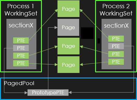
In this structure, the ProtoAddress points to another PTE named prototype PTE.
This prototype PTE, allocated in the kernel PagedPool, actually describes the current page state.
Since then, when removing a page, the OS just has to update the corresponding prototype PTE.
Now, a prototype PTE can itself present all the previously described states : valid, transition, paged, demand zero. Technically other states exists (see Prototype PTEs in Windows Internals 7th edition chaper 5 : Memory Management) but are not involved in virtual address translation.
For example, the next figure illustrates a prototype PTE in transition state, which means its PageFrameNumber still targets a physical page with valid content:
Subsection PTE
Concerning image file mapping, the system implements a special optimization relying on prototype PTEs. Indeed, these files includes several non-writable constant pages. This way, there is no need for the system to back up such pages in the paging files as they already reside in the original file.
To deal with this case, the system sets the PTE.u.Soft.Prototype flag in the targeted prototype PTE.
The corresponding structure for this PTE is then a _MMPTE_SUBSECTION defined as follows:
nt!_MMPTE_SUBSECTION
   +0x000 Valid             : Pos 0, 1 Bit    // 0
   +0x000 Unused0           : Pos 1, 3 Bits
   +0x000 SwizzleBit        : Pos 4, 1 Bit
   +0x000 Protection        : Pos 5, 5 Bits
   +0x000 Prototype         : Pos 10, 1 Bit   // 1
   +0x000 ColdPage          : Pos 11, 1 Bit
   +0x000 Unused1           : Pos 12, 3 Bits
   +0x000 ExecutePrivilege  : Pos 15, 1 Bit
   +0x000 SubsectionAddress : Pos 16, 48 Bits
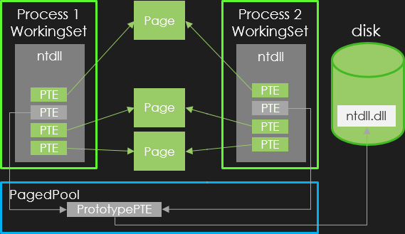
The following figure illustrates this case where a page from the ntdll.dll is removed from both working sets:
Without entering into details, the _MMPTE.u.Subsect.SubsectionAddress points to a _CONTROL_AREA structure, which itselfs points to a _FILE_OBJECT.
(To locate the page-content described by a _MMPTE_SUBSECTION, thea reader can have a look this rekall’s article).
Unfortunately, concerning subsection PTEs, their content cannot be accessed without reading the original image file on the file system.
VAD based PTE
A last optimization is implemented by Windows.
When the PTE value is null (_MMPTE.u.Long=0) the process Virtual Adress Descriptors (VADs) must be inspected to locate the corresponding prototype PTE (this state is named unknown in Windows Internals and VAD Hardware PTE in the rekall project).
The same case exists when the _MMPTE.u.Soft.Prototype flag is set and the PTE.u.Proto.ProtoAddress equals 0xFFFFFFFF0000 (this state is named Virtual Address Descriptor in Windows Internals and VAD Prototype PTE in the rekall project).
nt!_MMPTE_PROTOTYPE
   +0x000 Valid                : Pos 0, 1 Bit     // 0
   +0x000 DemandFillProto      : Pos 1, 1 Bit
   +0x000 HiberVerifyConverted : Pos 2, 1 Bit
   +0x000 ReadOnly             : Pos 3, 1 Bit
   +0x000 SwizzleBit           : Pos 4, 1 Bit
   +0x000 Protection           : Pos 5, 5 Bits
   +0x000 Prototype            : Pos 10, 1 Bit    // 1
   +0x000 Combined             : Pos 11, 1 Bit
   +0x000 Unused1              : Pos 12, 4 Bits
   +0x000 ProtoAddress         : Pos 16, 48 Bits  // 0xFFFFFFFF0000
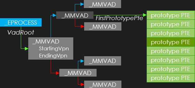
The following figure illustrates how we can access the desired prototype PTE in such cases.
First, this VAD-based case only happens in the context of a user process.
Starting from the corresponding _EPROCESS structures (in blue), we have to locate the corresponding memory area.
Such an area is called a Virtual Adress Descriptor (VAD) defined with the _MMVAD kernel structure.
Each process owns a set of VADs organized into a self-balanced AVL tree starting from the VadRoot field.
Briefly, each VAD has a starting address (StartingVpn standing for Starting Virtual Page Number) and an ending address (EndingVpn) field.
Three cases are possible:
- The wanted address is below the
StartingVpn- The left child (in red) is to be considered.
- The wanted address is above the
EndingVpn- The right child (in blue) is to be considered.
- Otherwise the wanted address is withing the range defined by
StartingVpnandEndingVpn- The desired VAD is found (in dark-gray).
Now each VAD exposes an array of prototype PTEs as FirstPrototype field.
As a prototype PTE stands for a 4KB page, it’s easy to compute the targeted prototype PTE (in dark-green in this example).
Finally, the obtained prototype PTE is processed as previously seen.
Mitigation of L1 Terminal Fault (Foreshadow)
Starting from august 2018, the previous virtual address translation approach evolved.
Indeed, just using the !pte kd command on a virtual address could output the following result:
kd> !pte 7ff743655000
... PTE at FFFFE93FFBA1B2A8
... contains 000020000891F860
... not valid
...   Transition: 891F
...   Protect: 3 - ExecuteRead
As you can see the corresponding PTE is not valid (value 000020000891F860).
It’s easy to verify that the content stands for a transition PTE with a PageFrameNumber of 0x20000891F.
But kd shows a different transition PFN value of 0x891F.
Where does this difference come from?
A complete answer is given by the Microsoft Security Response Center (MSRC): a new mitigation concerning a speculative execution side channel vulnerability known as L1 Terminal Fault (L1TF) was introduced.
In a nutshell, the official MMU behavior, as explained in the Intel manual, is different from the speculative one.
When the _MMPTE_HARDWARE.Valid flag is not set, the CPU speculatively tries to access the page targeted by the PageFrameNumber in the L1 cache.
If present, instructions are prefetched, which can lead to a leak of sensitive information like kernel addresses.
To mitigate this CPU flaw, Windows now ensures that each invalid PTE has a PageFrameNumber outside the limits of available physical memory.
This is achieved by the MiSwizzleInvalidPte function:
_MMPTE __fastcall MiSwizzleInvalidPte(_MMPTE pte)
{
  if ( gKiSwizzleBit )
  {
    if ( !(gKiSwizzleBit & pte.u.Long) )
      return (_MMPTE)(pte.u.Long | gKiSwizzleBit);
    pte.u.Long |= MMPTE_SWIZZLE_BIT;
  }
  return pte;
}
The gKiSwizzleBit global value is defined during system initialization in the MiInitializeSystemDefaults function:
KiSwizzleBit = 1i64 << (KiImplementedPhysicalBits - 1);
Note that this gKiSwizzleBit is not an official name but just a proposed one for this article.
The KiImplementedPhysicalBits value is initialized using the cpuid instruction to get the maximum amount of physical memory (see the KiDetectKvaLeakage function).
Summary
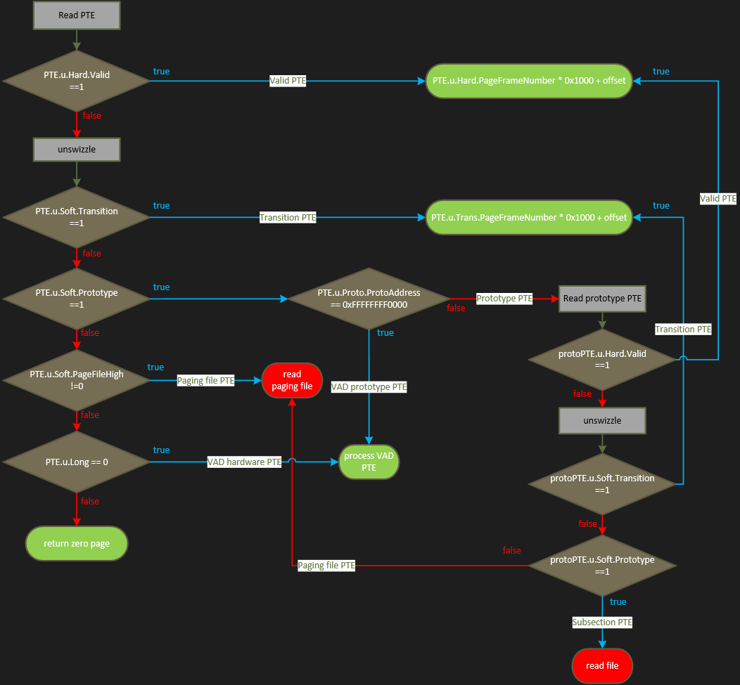
The whole PTE resolution algorithm can be summarized in the following figure:
We are now able to handle all the software PTE states involved in the Windows virtual address translation:
- in green, cases where we can access the content of the targeted page
- in red, the two remaining cases, which still require accessing the file system:
- paging files PTEs
- subsection PTEs.
IceBox and Windows memory access
Instead of looking for a way to parse the virtual disk for paging files (as rekall can do) and executables, IceBox focuses on a more practical approach.
In the ideal case, we’d like to boot a VM and access its physical memory without any particular configuration or user action.
Disabling the paging files
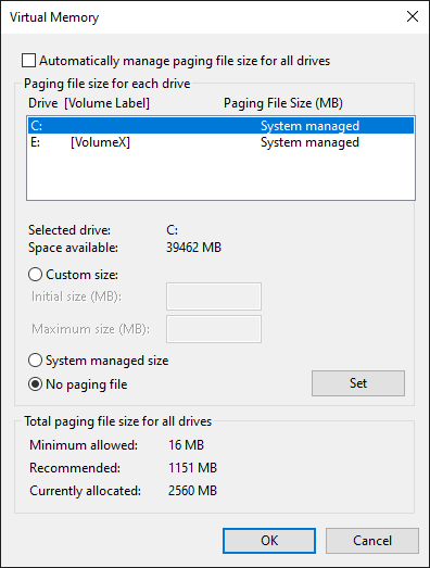
Disabling the paging files is a well known feature using the sysdm.cpl as illustrated in the following figure:
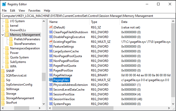
Modifications are saved in the registry under the \HKEY_LOCAL_MACHINE\SYSTEM\CurrentControlSet\Control\Session Manager\Memory Management key, with a multi-string value named PagingFiles as shown in the following screenshot:
Paging files are created by the first user process named smss.exe, which is launched during kernel initialization (Phase1InitializationIoReady).
Everything starts in the SmpLoadDataFromRegistry function where the SmpPagingFileList is built from the registry.
Each entry contains the path to a paging file (c:\pagefile.sys and e:\pagefile.sys in our example).
Later the SmpCreatePagingFiles function walks through SmpPagingFileList to finally invoke the NtCreatePagingFile syscall on each paging file.
To disable paging files in IceBox the NtCreatePagingFile function is disabled.
For stealth purpose, no hook is performed.
Instead, a temporary breakpoint is set on NtCreatePagingFile.
When triggered by smss.exe, the control flow is redirected to a RET instruction by modifying the RIP register.
Once initialized, smss.exe launches the first csrss.exe process.
This process start-up allow us to delete the previous breakpoint on NtCreatePagingFile.
Disabling subsection PTEs
To address this problem, let’s go deeper into how the system creates and maps _SECTION objects.
It starts with NtCreateSection and its subfunctions:
NtCreateSection
 NtCreateSectionCommon
  MiCreateSection
   MiCreateImageOrDataSection
    MiCreateNewSection
     MiCreateImageFileMap
In this last function, the interesting pseudo-code portion can be summed up as follows:
status = MiBuildImageControlArea(...,&FileSize,&pNewControlArea);
if (!NT_SUCCESS(Status)) goto CleanUp;
//...
if (IoIsDeviceEjectable(arg0_pFileObject->DeviceObject))
{
    bIsEjectable = 1;
}
//...
if (bIsEjectable)
{
    pNewControlArea->u.ImageControlAreaOnRemovableMedia = 1;
}
Basically, if the target device object is considered as ejectable, the ImageControlAreaOnRemovableMedia flag is set in the newly created control area.
This flag is then checked in the MiCreateNewSection.
When set, the MiSetPagesModified function is called.
This function updates the state of each PTE describing the section from prototype to transition.
As the paging file is disabled these PTEs will always stay in transition state, which is a state handled by IceBox.
In order to achieve this, the IoIsDeviceEjectable function needs to return true:
bool __fastcall IoIsDeviceEjectable(PDEVICE_OBJECT pDeviceObject)
{
  return (((pDeviceObject->Characteristics & FILE_FLOPPY_DISKETTE) == 0) & !_bittest(&InitWinPEModeType, 31u)) == 0;
}
Thus, we have two options:
- Force the
Characteristicsof the volume device to add theFILE_FLOPPY_DISKETTEflag. - Modify the
InitWinPEModeTypevalue.
The first option requires to detect when the device is created, to update as soon as possible its Characteristics.
The second option seems easier.
Indeed, the InitWinPEModeType is initialized in the Phase1InitializationDiscard function:
if ( Options && strstr(Options, "MININT") )
  {
    InitIsWinPEMode = 1;
    if ( strstr(Options, "INRAM") )
      InitWinPEModeType |= 0x80000000;
    else
      InitWinPEModeType |= 1u;
  }
This option corresponds to the Windows PE (WinPE) functionality. According to Microsoft, WinPE is a small operating system used to deploy, install and repair Windows desktop and server installations. As this system is launched from an ISO file, it makes sense that the subsection PTE limitation is not a problem with this option. Cherry on the cake, this option is present (at least) since Windows XP.
IceBox currently enables the WinPE mode by forcing this InitWinPEModeType global to 0x80000000 during the OS boot.
What about memory compression?
Memory compression is a feature introduced in Windows 10 and backported to Windows 8 and 7. This mechanism compresses private pages on client Windows versions to increase the amount of available memory. Memory Compression includes kernel and user parts:
- In the kernel, the core functionality is implemented in a dedicated component named the Store Manager (SM) (all the public and private kernel functions prefixed by
SmandSmp). - In user-space, the Superfetch service (
sysmain.dllhosted in asvchost.exeinstance) calls the SM by theNtSetSystemInformationto manage store.
For a complete description of how Memory Compression behaves, see Windows Internals 7th edition chaper 5 : Memory Management (MemoryCompression). As compression is just a memory optimization, we are just interested in disabling this feature.
The MemoryCompression process is created by the kernel with PsCreateMinimalProcess in the SmFirstTimeInit function .
Just before creating this process, the MmStoreCheckPagefiles function ensures at least one paging file exists, otherwise the status STATUS_NOT_SUPPORTED is returned.
By disabling the paging files, the memory compression feature is implicitly disabled.
Limitations
Of course, the previous modifications concerning paging files and the WinPE mode impact the system. First, disabling paging files presents several limitations:
- Paging files represent a second memory storage to virtually increase the physical memory size. Consequently, disabling paging files directly limits the total amount of available physical memory. This limitation can easily be overcome by increasing the physical memory of the Virtual Machine.
- In case of system crash, the paging files are involved to temporarily store the resulting crash dump. Disabling paging files prevents the crash dump from being created.
- As previously mentioned, memory compression requires paging files. Therefore, disabling paging files prevents from analyzing memory compression internals.
Second, from a stealth point of view, the WinPE mode can easily be detected. This point is currently not considered in our IceBox implementation.
Conclusion
This article focused on guest memory access from a VMI point of view. More precisely, we described some Windows virtual address translation internals and recent mitigations with regards to speculative execution side channels vulnerabilities called L1 Terminal Fault. This fine understanding of memory internals allows us to access any physical page as long as it is still present in memory. It also permits to highlight some cases where the pages are not mapped into the physical memory but only present on the file system.
We then described how VMI allows an automatic configuration of a Windows guest during its initialization phase to force any pages to be mapped in a persistent way into the memory. All these aspects are implemented in IceBox which automatically:
- Disables the paging files to avoid the paged-out mechanism.
- Enables the WinPE mode to avoid subsection PTEs which directly references pages on the disk.
Concerning the impact on the system, the induced modifications suffer minor drawbacks compared to the benefits of a full memory introspection.
Finally, you just have to boot your VM once with icebox, take a snapshot and have fun with memory!
