A gentle introduction to binary analysis and Ghidra's SLEIGH
This post serves as a text version of our presentation (available here) at Biere et Secu on 21/04/2026.
Binary executables are everywhere: firmware, desktop and mobile apps. They are fast and compact, but also difficult to understand. At their core, binary executables are just a sequence of raw machine code: 0s and 1s interpreted in the CPU as instructions. For that reason, this format is not ideal for human readability. Yet, in certain situations, for example malware analysis, we need to understand what a binary executable is doing. This is where disassembly comes in:
Disassembly
Disassembly is the process of translating machine code into human-readable assembly instructions.
For example, 0100100010000011011100000001000000101010 would become mov QWORD PTR [rax+0x10], 4.
This is essentially the opposite of what a compiler does. Indeed, a compiler translates human-readable code into machine code, while a disassembler tries to translate machine code into human-readable assembly.
At first glance, this might seem simple, it is not.
What makes disassembly hard
Intel’s x64 use variable-length instructions.
This means an instruction can be anywhere from 1 to 15 bytes long.
lock add QWORD PTR [rax+rdi*4+0x12345678],0x12345678 is encoded as F0488184B87856341278563412 while pushfq is encoded as 9c.
So, when looking at a sequence of bytes, a natural question arises:
Where do the program’s instructions start and end ?
Code vs data
To make matters worse, a binary is not only composed of instructions. It also contains data, that is, non executable bytes:
- Strings (“Hello, World”)
- Constants (3.141592)
- Metadata
These data bytes are in the same file as our instruction bytes and sometimes, both are intertwined.
For example, c39c could be a ret instruction followed by the instruction pushfq, or a ret instruction followed by the numeric constant 0x9c.
This leads us to a more complete question:
How do we know which bytes are instructions and which are just data ?
This problem is not just difficult, it is undecidable. It is impossible to make a program that solves it perfectly.
This would solve the Halting Problem (does a program terminate?), which is famously undecidable. Therefore, separating code from data is undecidable.
In practice, disassemblers rely on assumptions, heuristics and sometimes a human analyst’s gut. They do not get it right all the time.
From instructions to semantics
Reading assembly instructions is only the first step. What we really want, is to understand what the program does. This is known as a program’s semantics.
In practice, an analyst might want to known:
- Where a function begins and ends
- What values can a variable take
- What inputs are required to reach a certain point
To answer these questions, we often need to analyze the program, modifying it without changing its semantics.
In the most extreme case, the program was purposefully made difficult to understand and we need to deobfuscate it. This is the topic of my PhD.
Unfortunately, raw assembly is not ideal for that.
A single xor instruction from x64 can
- Read from memory and registers
- Perform both arithmetic and logical operations
- Modify multiple locations, sometimes even giving them undefined values
Another good example is the mov instruction which is famously Turing complete.
In short, instructions are too complex and too semantically coarse.
Intermediate Representation (IR)
To make analysis easier, tools translate assembly into a simpler language called an Intermediate Representation (IR). This might sound surprising, but it is often simpler to translate the original assembly program into another language (the IR) then analyze the IR, rather than just analyzing the original assembly.
You might wonder “How come ?”. Since we control the design of the IR, we can build it to our advantage
- By keeping it close to assembly, we guarantee that it’s easy to translate too
- Having few and simple instructions makes analysis easier. We might not control Intel’s design for
xor, but in our IR, axoris just axor.
You might notice the inherent compromise that comes with designing an IR.
- If it’s close to assembly, it’s easy to translate, but hard to analyze
- If it’s too abstract, it will be much simpler to analyze, but harder to translate too.
There is no one size fits all solution.
Examples of IRs
Several binary analysis frameworks use their own IR. To name a few:
- LLVM IR: widely used in the LLVM compiler. It has a hight abstraction level, making translating binaries to LLVM IR difficult. Nevertheless, it is used by binary analysis tools like Saturn / Remill / my internship work.
- P-code: used by Ghidra
- VEX: used in Angr
- DBA: used in Binsec
Case Study: Ghidra
Ghidra is a free and open-source binary analysis framework developed by the NSA. It supports many CPU architectures and relies on a common IR called P-code.
PCode
PCode is a “simple” IR with a small set of instructions (around 70).
It is very close to machine behavior, allowing the direct manipulation of both registers and memory locations.
It also does not have any hidden, implicit side effects. This means that to fully capture the semantics of a CPU instruction, multiple PCode instructions are necessary. This may seem inefficient, but it is intentional. The goal is clarity, not compactness.
A key advantage is that the same PCode is used across all of Ghidra’s supported architectures. This means analysis algorithms only need to be written once.
For example, an x64 ADD EAX, EDX would be translated to the following PCode:
CF = INT_CARRY EAX, EDX
OF = INT_SCARRY EAX, EDX
EAX = INT_ADD EAX, EDX
RAX = INT_ZEXT EAX
SF = INT_SLESS EAX, 0:4
ZF = INT_EQUAL EAX, 0:4
$U28080:4 = INT_AND EAX, 0xff:4
$U28100:1 = POPCOUNT $U28080:4
$U28180:1 = INT_AND $U28100:1, 1:1
PF = INT_EQUAL $U28180:1, 0:1
While an AARCH64 add w0, w1, w0 would be translated to:
$U12180:4 = COPY w0
tmpCY = INT_CARRY w1, $U12180:4
tmpOV = INT_SCARRY w1, $U12180:4
$U12280:4 = INT_ADD w1, $U12180:4
tmpNG = INT_SLESS $U12280:4, 0:4
tmpZR = INT_EQUAL $U12280:4, 0:4
x0 = INT_ZEXT $U12280:4
You can directly see the generated PCode in Ghidra’s GUI:
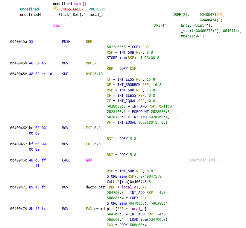
The rest of this article is going to be dedicated to understanding how we can translate machine code into PCode.
Lifting with SLEIGH
The process of translating machine code to an IR is called lifting, and in Ghidra it is handled by SLEIGH. SLEIGH is a domain-specific language, used to describe architectures. A single SLEIGH specification is used both for: disassembly and lifting. It is noteworthy that only the PCode is used for further analysis.
SLEIGH Basics
Let’s consider the following SLEIGH specification:
define endian=little;
define space ram type=ram_space size=4 default;
define space register type=register_space size=4;
define register offset=0 size=4 [ r0 r1 r2 r3 r4 r5 r6 r7 ];

define token instr(16)
    op=(0,5)
    mode=(6,9)
    reg1=(10,12)
    imm=(13,15)
    reg2=(13,15)
;
attach variables [ reg1 reg2 ] [ r0 r1 r2 r3 r4 r5 r6 r7 ];

op2: reg2 is mode=0xa & reg2 { export reg2; }
op2: imm is mode=0xb & imm { export *[const]:4 imm; }
op2: [reg2] is mode=0xc & reg2 { tmp = *:4 reg2; export tmp;}

:and reg1,op2 is op=0xa & reg1 & op2 { reg1 = reg1 & op2; }
:xor reg1,op2 is op=0xb & reg1 & op2 { reg1 = reg1 ^ op2; }
:or reg1,op2 is op=0xc & reg1 & op2 { reg1 = reg1 | op2; }
We will break this down step by step.
Address Spaces
The specification starts with some general settings (like endianness) before describing address spaces. You can think of address spaces as non overlapping memory regions.
define space ram type=ram_space size=4 default;
define space register type=register_space size=4;
In our example, we define two address spaces: ram and registers.
The ram address space will be used to describe the actual memory.
Meanwhile, the registers address space is a virtual space used to define the CPU registers.
In SLEIGH (and PCode) registers are not special values, they are simply pointers in this register space.
Talking about registers, let’s define some:
define register offset=0 size=4 [ r0 r1 r2 r3 r4 r5 r6 r7 ];
Here, we defined 8 registers (r0 to r7), each 4 bytes wide.
Internally, they will be laid out in the registers address space like this: r0 at offset 0, r1 at offset 4, all the way to r7 at offset 28.
Tokens and Fields
Next, we define how raw bytes are interpreted:
define token instr(16)
    op=(0,5)
    mode=(6,9)
    reg1=(10,12)
    imm=(13,15)
    reg2=(13,15)
;
A token is a sequence of bytes used to decode machine instructions.
In our example, the token instr is 2 bytes wide (16 bits).
Tokens are then divided into fields, each representing a sub-range of bits in the token.
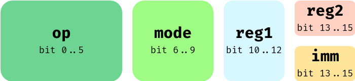
The same bits can be in multiple fields.
Here, the last 3 bits can be interpreted either as the imm field or the reg2 one.
Given bytes like 0xCAFE for our token, each field maps to a numerical value.
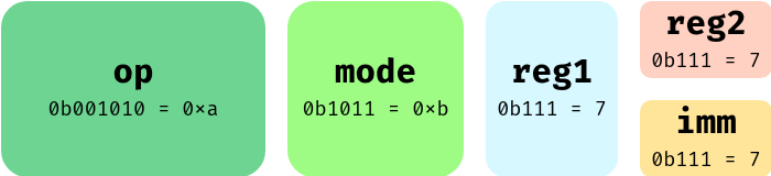
For some fields, like op or imm, a simple numeric value is enough.
However, for others we can treat their numeric value in a table to change their value.
attach variables [ reg1 reg2 ] [ r0 r1 r2 r3 r4 r5 r6 r7 ];
In our case, reg1 and reg2 should be treated as indices in a table of registers.
For example, if the field reg1 matched on 0b111=7, it would not take the value 7 (unlike what imm would have done).
Instead, reg1 will be interpreted as the value at index 7 in the table; in this example, that value would be r7.
Constructors
Instructions are defined using constructors, which include:
- Display section used to build the disassembly output
- Constraint section used to select a constructor
- Semantic section used to build the PCode output
Let’s consider the following constructor:
:and reg1,op2 is op=0xa & reg1 & op2 { reg1 = reg1 & op2; }
Its display section is and reg1,op2.
This simply describes the appearance of the disassembly string.
reg1 and op2 will be replaced by their values.
Then, the pattern is op=0xa & reg1 & op2.
This means that for an instruction to be an and, the field op must have the value 0xa and we must be able to construct both reg1 and op2.
Finally, the semantics for this instruction is the following PCode code: reg1 = reg1 & op2;.
Again, reg1 and op2 will be replaced by their values.
Tables
A same instruction can often be applied to registers, memory locations and immediate values. To avoid duplication, SLEIGH uses tables. A table is simply a set of constructors.
In our example, we define the op2 table which may represent multiple operand forms:
op2: reg2 is mode=0xa & reg2 { export reg2; }
op2: imm is mode=0xb & imm { export *[const]:4 imm; }
op2: [reg2] is mode=0xc & reg2 { tmp = *:4 reg2; export tmp;}
When we try to match op2, we are trying to match any constructor in op2.
In other words, tables can be seen as an OR of multiple constructors.
Finally, you might notice the special keyword export in the semantic section.
It simply describes which PCode value should be used to replace op2 in the semantic section.
Think of it as a return statement.
Putting it together
Using the previous SLEIGH spec, here are the constructors that are matched for the following values: 0xcafe, 0x8b52:
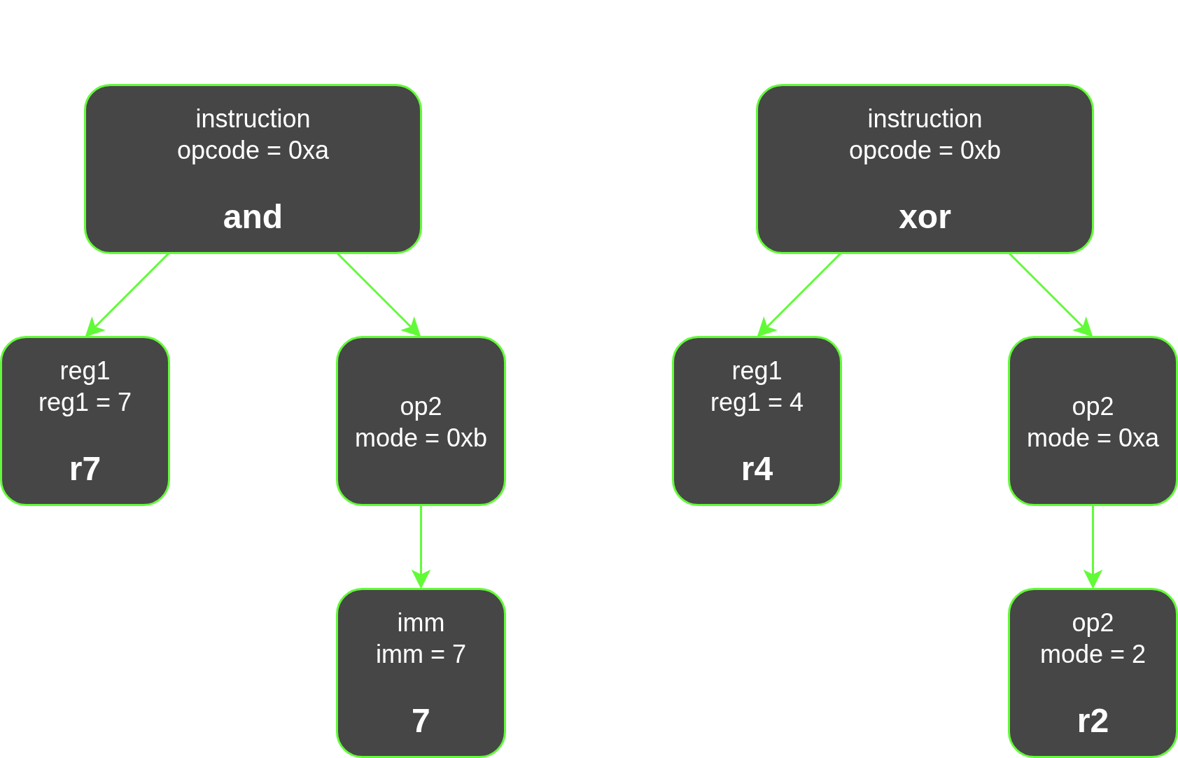
We can then see how the replacement values are propagated:
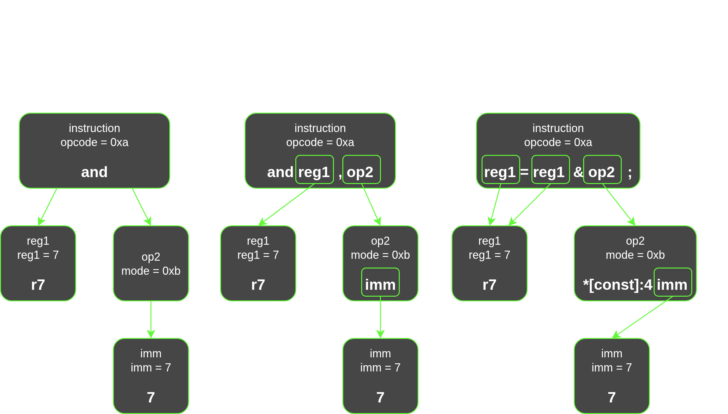
And with that, we have successfully translated machine code into PCode!
Takeaway
This post served as a gentle introduction to binary analysis. The most important takeaways are not necessarily the nitty gritty of Ghidra and SLEIGH.
What matters is this:
- Raw machine code is hard to analyze
- Assembly is still too complex
- Intermediate representations simplify everything
In Ghidra:
- Instructions are lifted into PCode
- Analysis operates entirely on this IR
- The translation is defined using SLEIGH
If you are analyzing binaries directly at the assembly or byte level, you are making your life harder than necessary.