Cyber Apocalypse 2021 3/5 - Off the grid
Off-the-grid was the 4th hardware challenge of the Cyber Apocalypse 2021 CTF organized by HackTheBox. We were given an Saleae trace and schematics to analyse. Thalium was one of the very first of 99 players to complete it.
Analyzing the Saleae capture
First thing first, what does the schematic tell us ?
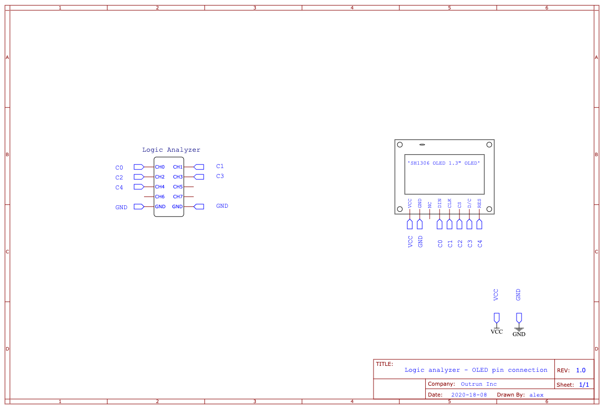
We have a hardware logic analyzer and one of those cheap OLED screens. In our case, it is an SH1306, with a 128x64 pixels grid (1.3"). The schematic shows us how the logic analyzer is connected to the screen’s command pins. There is still one thing missing, not given in the archive. A file you almost always need when doing hardware reverse: The Datasheet. Just google “SH1036 datasheet” and you end up with a link like this one. Armed with these information, let’s take a look at the trace now.
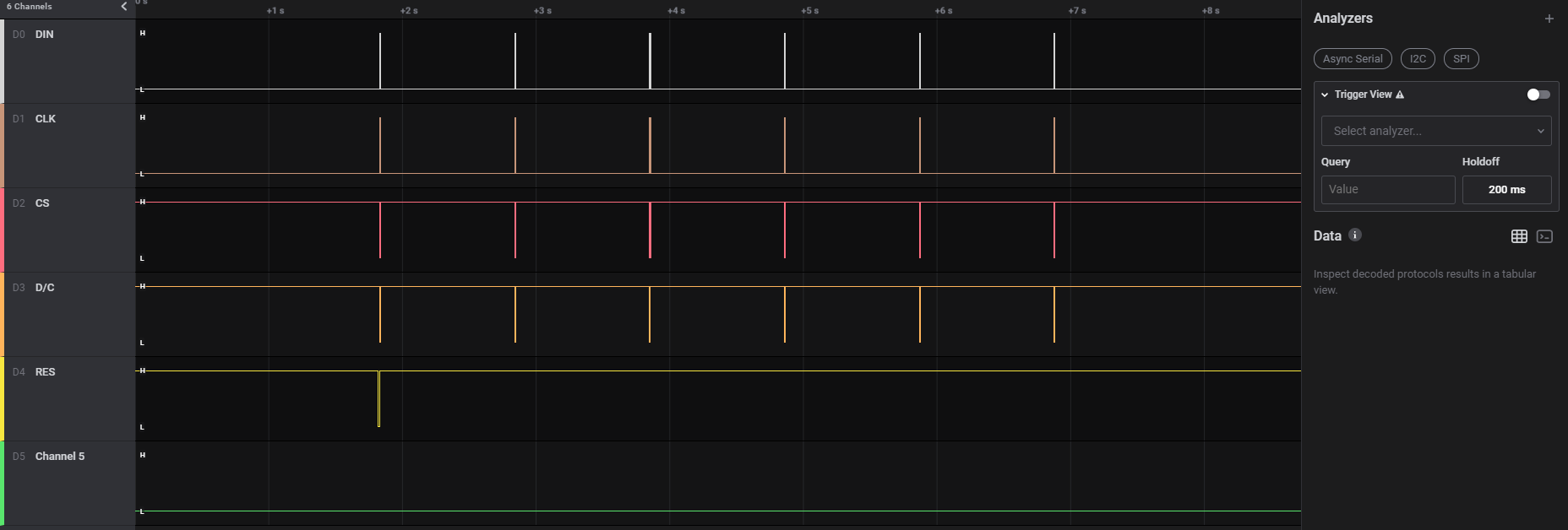
As you can see on the left, I already labeled the 5 first channels using what I learned from the schematic. There are 6 group of lines, each one aproximatively 1 second appart. We could then assume that 6 different images were drawn on the screen. But what are they, and how do you draw something on the SH1306 OLED screen ? Time to dig into the datasheet.
First of all, what does the different channel / pin do ? DIN stands for “Data In”, CLK for “Clock”, CS means “Chip select”, D/C “Data / Command” and RST “Reset”. With DIN and CLK, we now know it uses some kind of synchronous communication. D/C tells us that you can send control commands. Without reading the documentation, we can think of commands like “clear screen” or “next data written will be on that part of the screen”.
Let’s get back to the documentation of the communication protocols the screen can understand, at the beginning of 8th chapter. There are 5 of them :
- 8-bit 8080
- 8-bit 8060
- 3-wire SPI
- 4-wire SPI
- I²C
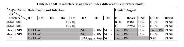
8-bit communication needs an… 8 bit bus. In our case, we only use one bit on the DIN channel. Only the 2 types of SPI and I²C use a pin labeled “SCLK”. On these 3 left, I²C uses 2 pins for data. That leaves us with SPI. But which one ? If you look closely on the “D/C” column, only 4-wire SPI uses it. 3-wire SPI requires it to be on “LOW” at all time.
We know which communication bus is in use in our case. How can we extract the data ?
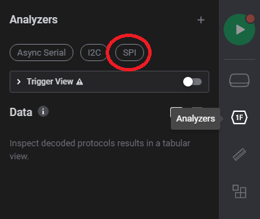
Saleae software comes with many analyzers. To select one, click on the “analyzer” icon on the left. By default, you have a quick access to the most used bus/protocols: UART, I²C and SPI. Select SPI.
It then asks you the settings to decode a SPI trace. Set them as in the screenshot below
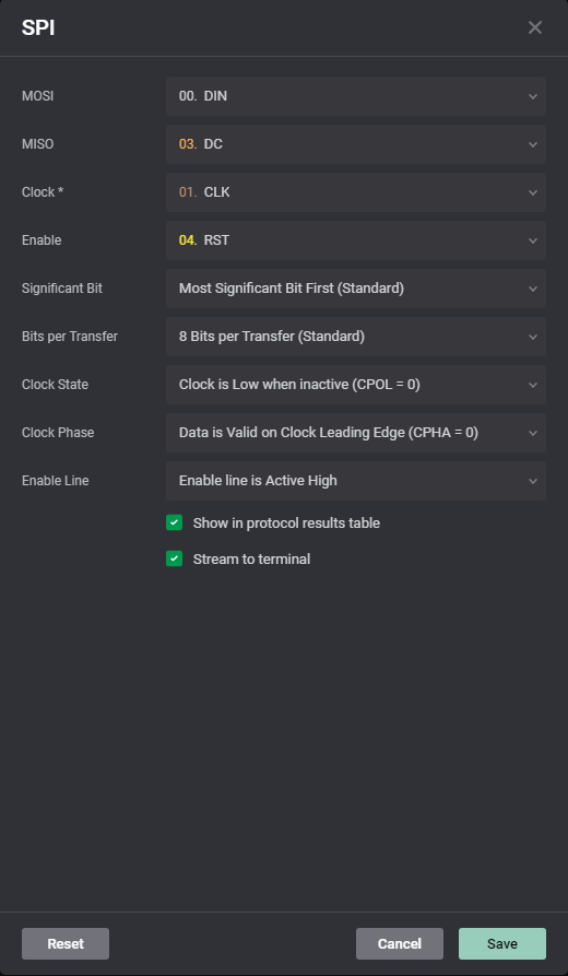
The clock setting is… well, CLK channel. We arbitrarily chose RST for the “Enable” setting, since it stays high all the time. MOSI and MISO can be inverted, it will just change the way you parse the extracted data. You end up with something like this:
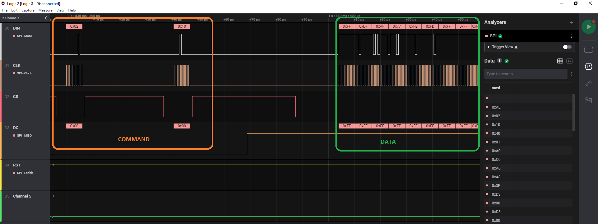
And voila !
The data sent on the wire is a command if the D/C channel is LOW and handled as data otherwise. We can use the SPI analyzer to export a trace file:
$ head trace.txt
Time [s],Packet ID,MOSI,MISO
1.828613640000000,0,0xAE,0x00
1.828668500000000,0,0x02,0x00
1.828711540000000,0,0x10,0x00
1.828753260000000,0,0x40,0x00
1.828794320000000,0,0x81,0x00
1.828834820000000,0,0xA0,0x00
When the “MISO” column value is 0, it’s a command. When it’s 0xFF, it’s data. To extract the images drawn on the screen, all we have to do is to parse this file and keep the lines with a MISO value of 0xFF. But remember, there are potentially 6 images drawn 1 second apart. As each line also has a timestamp, it’s really easy to separate each image.
We’ve got the data, good. But… how can we “render” it without an OLED screen ???
Rendering the screens
The trace contains six different bursts:
- a new burst is sent each second
- bursts are delimited with the
b0 02 10control sequence
For each burst corresponds a screen rendering. For each burst subtrace, we can extract the data sent from the master to the slave input (MOSI line):
import sys

with open(sys.argv[1], "rt") as fh:
    for line in fh.readlines():
        time, pid, mosi, miso = line.strip().split(",")
        if miso[-2:] != "00": # filter commands
              print(mosi[2:], end="")
Using this script, we obtain the hexdump the screen must render. The SH1306 is very similar to the well-known SSD1306, their rendering process is equivalent. The screen renders a 128x64 bitmap from the top-left pixel in a vertical fashion.
Many tools exist to convert an image to a proper bitmap for those tiny OLED screens. Image2cpp is one of them but it also allows to preview the byte array, which in our case, will allow us to decode the bursts into 128x64 images:
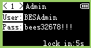 | 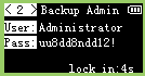 | 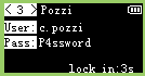 |
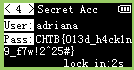 | 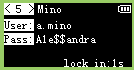 |  |
We can read the flag within the 4th screen: CHTB{013d_h4ck1n9_f7w!2^25#}